Reading DF-3 ALCO FA-1’s

Reading DF-3 #301Reading DF-3 #305b


Number Built RDG Class HP Engine House Assignment
300 6/48 DF-3 1600
300 B 6/48 DF-3 1600
301 6/48 DF-3 1600
301 B 6/48 DF-3 1600
302 6/48 DF-3 1600
302 B 6/48 DF-3 1600
303 6/48 DF-3 1600
303 B 6/48 DF-3 1600
304 6/48 DF-3 1600
304 B 6/48 DF-3 1600
305 6/48 DF-3 1600
305 B 6/48 DF-3 1600

References:
Reading Diesels Volume 1 The First Generation – by Dale Woodland

Photograph’s from George Losse Collection either scaned from negatives or prints.

The ORER’s

ORER – April 1956

Purchasing this ORER was one of the first steps in focusing my modeling efforts. For those that do not know about these, they list all the revenue freight cars for every railroad at the time of their publishing, Every one.

I used to refer to this as the “Bible for Modeling.”

When I was modeling the Elmira Branch in the late Spring of 1956, a car had to be listed in here or it did not belong on the railroad.

The information here is different then just knowing a railroad had the car, it tells you haw many they had on the roster at that time. That is very important information for trying to get the right proportions of cars modeled.

ORER – October 1953

When I made the switch to model the Reading I researched what locomotives I wanted to model and found the point in time that had the most of them on the roster at the same time. This turned out to be the middle of 1953. So I needed a “New Bible.”

This ORER for October 1953 shows different cars on the roster than the April 1956 ORER does. Just three yaears difference and there is a big difference in the cars which were retired by 1956 and the classes that were being built to replace them.

ORER – January 1952

This is now the “Bible” for my railroad. If it’s listed in here than I can have it on the railroad.

It’s also is the heart of the “By the Number” idea for modeling freight car fleets. It more important to know how many cars of a particular design a railroad owned as of Jan 1952, then just know that they owned them.

Reading Locomotives for the Layout


When I made to choice to model the Reading, I knew I had two choices, either have my modeling time after the last of steam or I was going to have to build some steam locomotives. There has not been many brass models imported in O scale of Reading steam locomotives. One reading fan suggested “buying a bunch of T-1’s and model 1956 because nothing else has been imported.”

When I was focused on the Elmira Branch of the PRR, I was also focused on 1956 as the date to model. When I first made the choice to model the Reading, I shifted my focused time period to 1953. All of the first generation diesel locomotives I liked were on the roster. And there were only a few Steam locomotive classes left running.

Well as luck would have it, I was able to trade some of my surplus PRR equipment for an SGL Reading G3. They only lasted on the line until the Summer of 1952 and then they were bumped from the King Coal by a pair of GP7’s. I’ve read that they lasted until September of that year even though the GP7’s which replaced them arrived in July. After that point the G3’s were transferred to South Jersey to run out their service life on the PRSL.

So that has set my time to the Summer of 1952.

Steam Classes

Left on the roster in 1952 were I9-sc’s, I10’s, K1-sd/e’s, N1-sd’s, G2-sa’s, G3’s and T-1’s.

The T-1‘s do not seem to show up in the photos West of Tamaqua until 1956-1957. They ran through the mainline to Pottsville and into Saint Clair. There is a really nice O Scale model of a T-1 done by Overland back in the 1990’s. There was also a nice Bob Jones’ Kit for a T-1 that was produced before the Overland run. The finding of a nice Overland T-1 has prompted the move of modeling location to Schuylkill Haven on the line to Pottsville.

SGL imported the Reading G3 back around 2000. While not super detailed, it does have enough detail to be a good place to start. One arrived on my roster in a trade for some of that surplus PRR equipment.

The N1-sd‘s, were built between 1917-1919 and are dimensionally close to a USRA 2-8-8-2. That is my starting point, I have a pair of Sunset N&W Y-3’s that are the going to become Reading locomotives.

The K1-sd/e‘s will have to be built. I found the the wheelbase is very close to that of the Sunset I1sa’s. With modifications to the Sunset frame, new boilers and new tenders, they will take shape.

The I10 uses almost the same wheel base as the PRR H10 so I plan to use the Central Locomotive Works H10 mechanism for this conversion.

The I9-sc was an I9 that was rebuilt with the running gear from the I10’s that became T1’s. So this too will use the Central Locomotive Works H10 mechanism for the conversion.

Diesel Classes

Seen in the photos from 1952 in the Shamokin Division were:  Road Power EMD FT’s, F3’s, F7’s, ALCO FA1’s and Baldwin AS-16’s, Switchers were EMD NW2’s Baldwin VO-1000’s and DS4-4-1000’s.

EMD FT’s:
O Scale is blessed with a couple of choices for EMD FT brass models, Overland or Hallmark. The Hallmarks are detailed for Santa Fe units so they would require some correcting. But they usually show up at good prices at the shows. Overland are a newer model imported in the 90’s and the details are much cleaner but they cost a little more. I was lucky to find a pair at a very good price.

MTH also makes a 3-rail version of an EMD FT, but it is not a scale model. I owned a pair, so I was able to see and measure them first hand.

EMD F3 & EMD F7:
There have been a number of O scale EMD F3 & F7 models available both as kits and brass imports. I am using a combination of Overland F3’s and P&D F3’s and F7’s.

ALCO FA-1’s:
There are again a number of options here in O scale.  Central Locomotive Works has made brass kits for them since before I was born. Key is about to import them, but their price point is not in my hobby budget. Overland has imported them in the past and that is what I have on my shelf.   Also Custom Brass and Sunset both have imported them in the past. I was going to use the Custom Brass models until I found an A-B-A set of the Overland models at a great price.
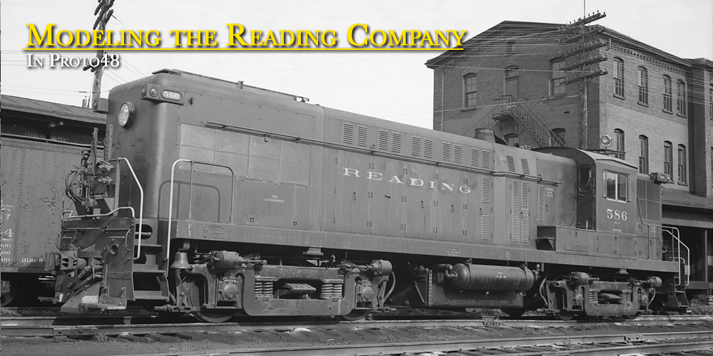
Baldwin AS-16’s:
The Overland AS-16 is THE option for modeling the Baldwin AS-16’s. The model was imported in the mid 90’s. They do show up at shows and on ebay every so often. So far the models I have found me in trades and one purchase. Overland produced both the early car body design and what modelers refer to as the ’53 body or high hood version.

Again, MTH has produced a 3-rail version that they call a Baldwin AS 616, but the hoods are too wide and too tall, they would require far too much work to correct them.

EMD NW2
All Nation has produced a white metal version almost as long as the prototype has existed. The All Nation model looks like 1940 technology. These have also been produced in brass by a couple of importers over the years.

I started building an NW-2 by combining an All Nation body on top of an Atlas SW9 frame. Life is way too short! I’m now looking for one of the brass imports to cross my path at a good price…..

Baldwin Vo-1000, DS4-4-1000:
I am using a pair of Car Works VO-1000’s and plan to back-date Rich Yoder’s S12 into the DS4-4-1000.

Weaver also make a nice model of the VO-1000 with curved insets in the walkways.

ALCO RS-3‘s and EMD GP7‘s:
While plentiful on the Reading, they did not venture into coal country much at this early date in freight service. That would change as time moves on and second generation diesels hit the roster.

Passenger service is a different story. The RS-3’s and the Gp-7’s did run in passenger service to Pottsville during this period.


Archer Transfers

On the Reading AS-16’s there were four rows of louvers under the engineer’s side air intake on the long hood, as seen on this detail of my brother’s drawing. These are missing on my pair of Overland AS-16’s. I’m not going to punch them in the brass sheeet and the thoght of cutting them into the sheet does not appeal to me either.

I thought this would be a good test for Archer Fine Transfers new surface details #36 O Scale 14″ Louvers and #37 O Scale 6″ Louvers. So I ordered them in last week. I have to say that they arrived a couple of days after placing the order on their website. I had ordered their rivets before but had not had a chance to use them yet.

I thought it would be a good idea to test them out before using them on the model. Even though these sheets are a little expensive there are plenty of louvers on the sheet.

They are handled just like decals but they are more fragile than decals. I soaked them in water until they released from the backing paper and then applied them to a test sheet of brass. They adheared fine, I did use Champs setting solution on them after they had dried.

For my needs for the AS-16 niether size is really correct. So I experimented with cutting the 14″ down to 8″ width. My first attempt did not work as I slide the blade down the decal. This cause the ends to chip away. I did say these details are fragile. My second attempt worked much better, I cut through the decals in a chopping motion and did not have any chipping of the detail.

Here is the test in primer. As I mentioned the left column, the 6″ louvers are spaced too far apart and are too narrow. The middle column is the 14″ louvers. They are close to the correct spacing but are too wide. The third column is the cut down 8″ column from the 14″ details. There is a hint of overlap in this image but remember column one is 1/8 of an inch wide, so they are reproduced here at about 400% of the actual size.

I like them. I’ll try them out on the Baldwins in the next couple of days.

Reading K1 – A New Tailbeam

Here is a quick photo-show of last weekend’s work making of the tailbeam. The work was done under the guidence of Matt Forsyth. I can’t thank him enough for making the machine work seem easy.

Sunset Frame in the vise, the two tail pieces have been heated and removed.

The toughest part of the operation. Putting a hack saw on the models frame.

With the tail section removed the hack saw cut is trued up in the milling machine.

Milling the step in the rear of the frame.

Cutting in two directions now. Milling the step and the face at the same time. You can still see some of the solder that held on the tail sections of the Sunset frame.

Continuing to cut the step back until the paint that was at the top of the step is removed.

Milling the step into the block.

Testing the fit of the frame into the step.

Starting the fly cut to thin down the block. I will remove the material down to the scribed line.

Still flycutting the block. You can see we are getting closer to the line on the block.

Milling the center slot in the tailbeam.

Tailbeam and frame are set together. The template for the side holes is in front. The shapes will be transfered to the tailbeam.

Back in the milling machine the corners of the holes are being plunge-cut. You can see the layout lines scribed on the side.

After all the side holes are opened up the angle cut is being done to the tailbeam.

The tailbeam and frame are clamped together and checked for alignment. Once straight, they were turned upright and soldered together.

After soldering the two together the tailbeam is machined to the finish size of the sunset frame.

Here Matt is finishing up the side of the frame with a file.

Just think only four more frames to go……

Reading K1 – Work Starts

K1 Frame starts to take shape. Sunset I1sa frame in back.

Well I’ve had my first lesson on the milling functions of my Sherline lathe/milling machine. I just spent a nice weekend up above Scranton learning how to use the machine. My friend Matt Forsyth was patient enough to guide, teach and watch me timidly use the machine. I did get better as we did more.

The project was to make a new tail-beam for theframe of the RDG K1 2-10-2. Here you see a photo of the progress. The new tail-beam has been made and attached to the frame (the next Sunset PRR I1sa donor frame is pictured behind). It’s missing the main driver because that is part of the next work on the model, changing the main driver to a disc driver. More on that later.

One of the toughest things about the process was taking a hack saw to the rear of the I1sa frame to start the project.