Reading K1 Progress

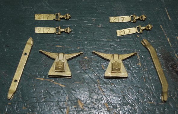
The trailing truck parts from CLW

I haven’t posted anything on the K1 project in a while. It has been sort of almost on hold.

I found the above parts for the trailing trucks. But it wasn’t a complete truck, and I wasn’t sure who made it. I sent emails out to a number of folks asking if they knew who made the parts and if anybody had any more.

Joe Foehrkolb identified the parts as Central Locomotive Works’ parts. After a couple of emails with Lou the parts were ordered. Jim Mucka was a big help also in giving me copies of the parts lists for CLW. It was very easy to talk to Lou with the correct part numbers. I wouldn’t have blamed Lou if he didn’t want to talk to me without the part numbers, I can’t imagine trying to describe these parts in an email. Well that was the begining of May, the parts are still a few weeks out. But they are coming, that’s the most important thing.

I also ran into a bit of a problem with tender trucks. I ordered a pair of their 584 on their website which lined up perfectly on the plan. When I went back to get more, they were out of stock and they were not sure if they would be re-run. I have since brought my truck total up to four. I still need one more set.

This is all part of the fun of building in O scale.

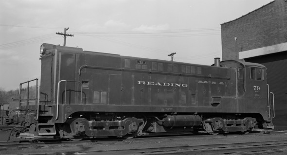
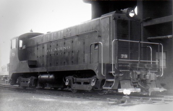
Baldwin VO-1000 #79

Reading OE-10 #79 at Gordon

One of the switchers I’ve chosen to model is Reading class OE-10 #79. It was a Baldwin VO-1000 switcher assigned to Gordon, PA during my modeling time-period.

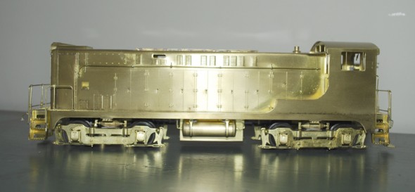
I’m going to use a Car Works VO-1000 model as the starting point. Car Works imported the VO series back in the early 90’s. They imported three versions, “VO-1000 1942-1944 #Curved Walks,” “VO-1000 1945-1947 Straight Walks” and a “DS4-4-1000 with FLat Grill.” They have a Weaver chain drive with Pittman motor. Out of the box they run fine. I may explore using a different drive set-up.

Looking at the fireman’s side there are shutters in two of the engine compartment doors, they will need to be added. The exhaust stack needs to be extended. I will need to add a cover for the radiator. Since my model has broken solder joints on one of the foot-boards at each end I think all four need to come off, be cleaned up and re-soldered back on.

Fireman's side of the Car Works VO-1000

Fireman’s side of the Car Works VO-1000

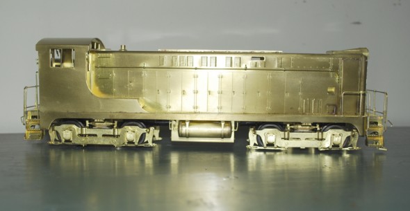
Looking at the engineer’s side of the locomotive. There does not appear to be many changes needed. I’ll have to add a number board to the lower part of the radiator screen. This view shows the radiator cover removed in 1956, so maybe I don’t need to add it. The Reading rain gutters will need to be added to the cab roof.

Reading #79 at Shamokin, PA 1956

Engineer's Side of the Car Works VO-1000

Engineer’s Side of the Car Works VO-1000

Reading K1 – A New Tailbeam

Here is a quick photo-show of last weekend’s work making of the tailbeam. The work was done under the guidence of Matt Forsyth. I can’t thank him enough for making the machine work seem easy.

Sunset Frame in the vise, the two tail pieces have been heated and removed.
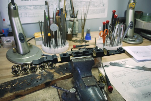
The toughest part of the operation. Putting a hack saw on the models frame.
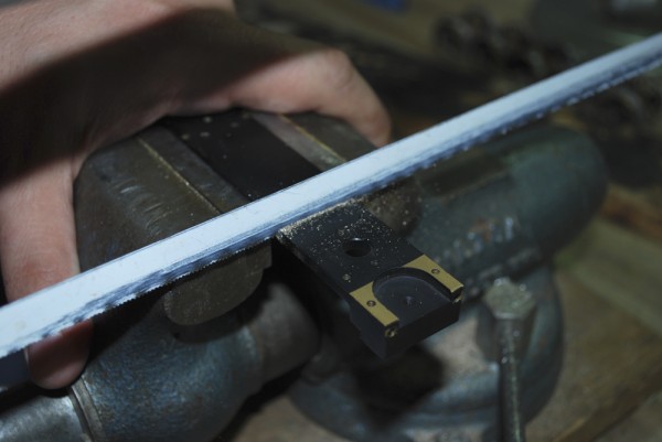
With the tail section removed the hack saw cut is trued up in the milling machine.
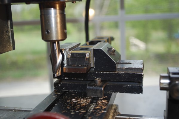
Milling the step in the rear of the frame.
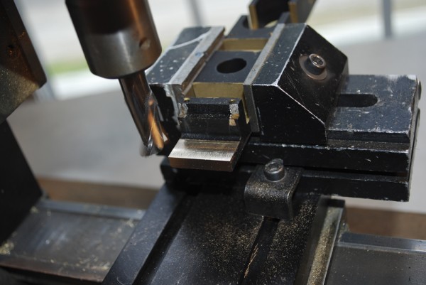
Cutting in two directions now. Milling the step and the face at the same time. You can still see some of the solder that held on the tail sections of the Sunset frame.
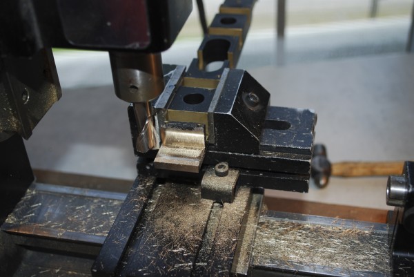
Continuing to cut the step back until the paint that was at the top of the step is removed.
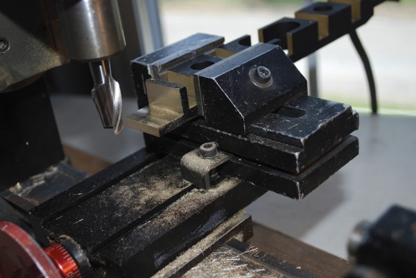
Milling the step into the block.
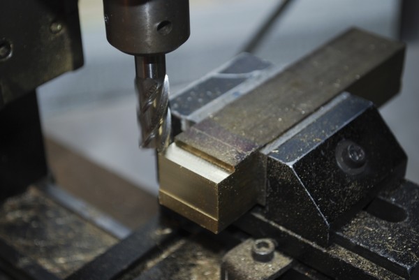

Testing the fit of the frame into the step.
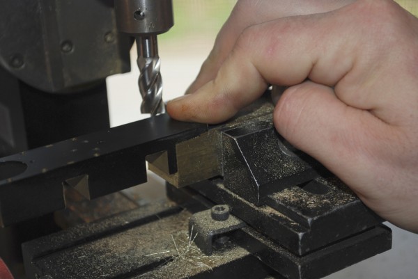
Starting the fly cut to thin down the block. I will remove the material down to the scribed line.
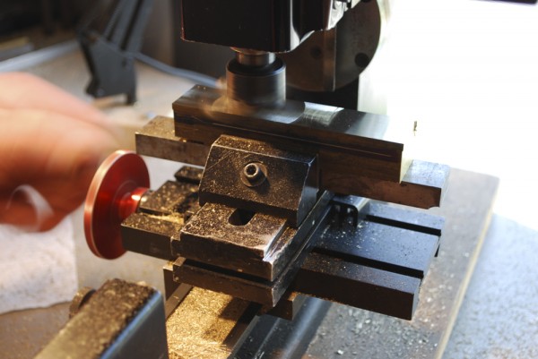
Still flycutting the block. You can see we are getting closer to the line on the block.
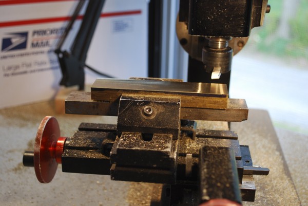
Milling the center slot in the tailbeam.
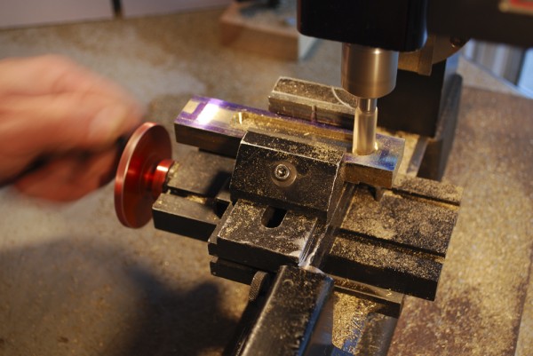
Tailbeam and frame are set together. The template for the side holes is in front. The shapes will be transfered to the tailbeam.
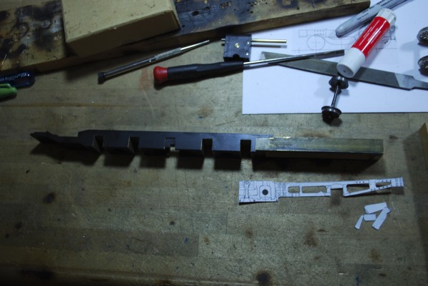
Back in the milling machine the corners of the holes are being plunge-cut. You can see the layout lines scribed on the side.
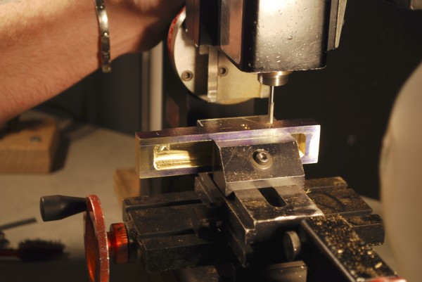
After all the side holes are opened up the angle cut is being done to the tailbeam.
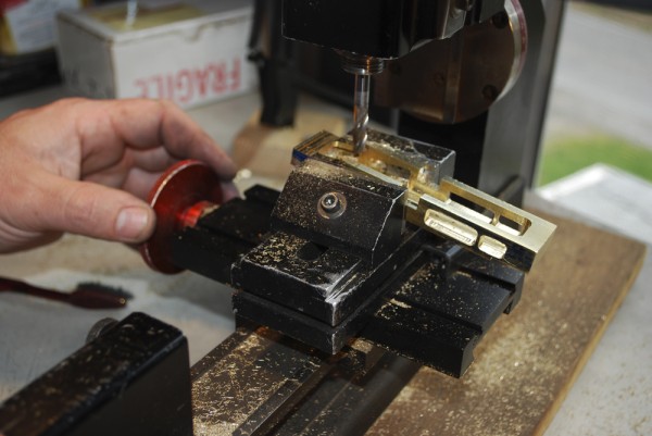
The tailbeam and frame are clamped together and checked for alignment. Once straight, they were turned upright and soldered together.
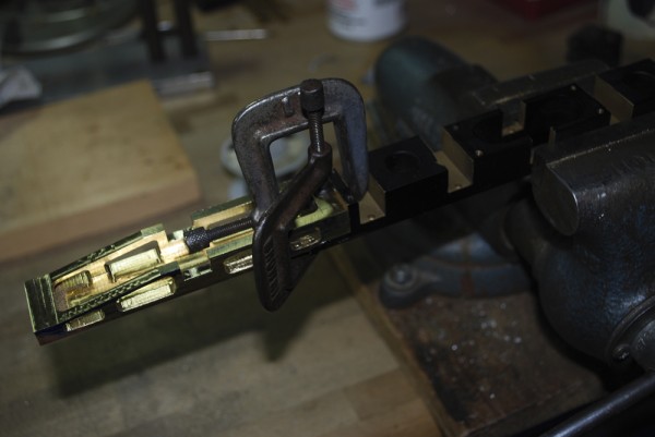
After soldering the two together the tailbeam is machined to the finish size of the sunset frame.
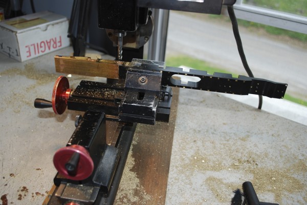
Here Matt is finishing up the side of the frame with a file.
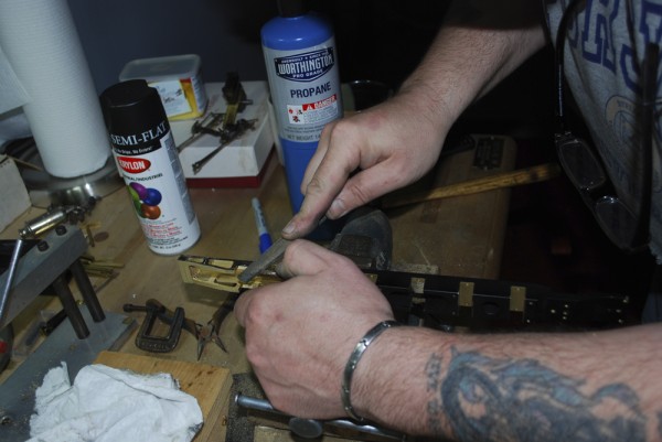
Just think only four more frames to go……
Reading K1 – Work Starts

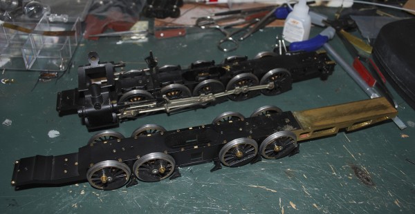
K1 Frame starts to take shape. Sunset I1sa frame in back.

Well I’ve had my first lesson on the milling functions of my Sherline lathe/milling machine. I just spent a nice weekend up above Scranton learning how to use the machine. My friend Matt Forsyth was patient enough to guide, teach and watch me timidly use the machine. I did get better as we did more.

The project was to make a new tail-beam for theframe of the RDG K1 2-10-2. Here you see a photo of the progress. The new tail-beam has been made and attached to the frame (the next Sunset PRR I1sa donor frame is pictured behind). It’s missing the main driver because that is part of the next work on the model, changing the main driver to a disc driver. More on that later.

One of the toughest things about the process was taking a hack saw to the rear of the I1sa frame to start the project.